Running Simulations¶
Open the simulation parameters dialog with the Configure toolbar tool (the title is Xyce Simulation). Parameters are organized in a vertical tab bar on the left, grouped by domain:
- DC —
.OP,.DC - Time-domain —
.TRAN - Frequency-domain —
.AC,.NOISE,.HB,.LIN
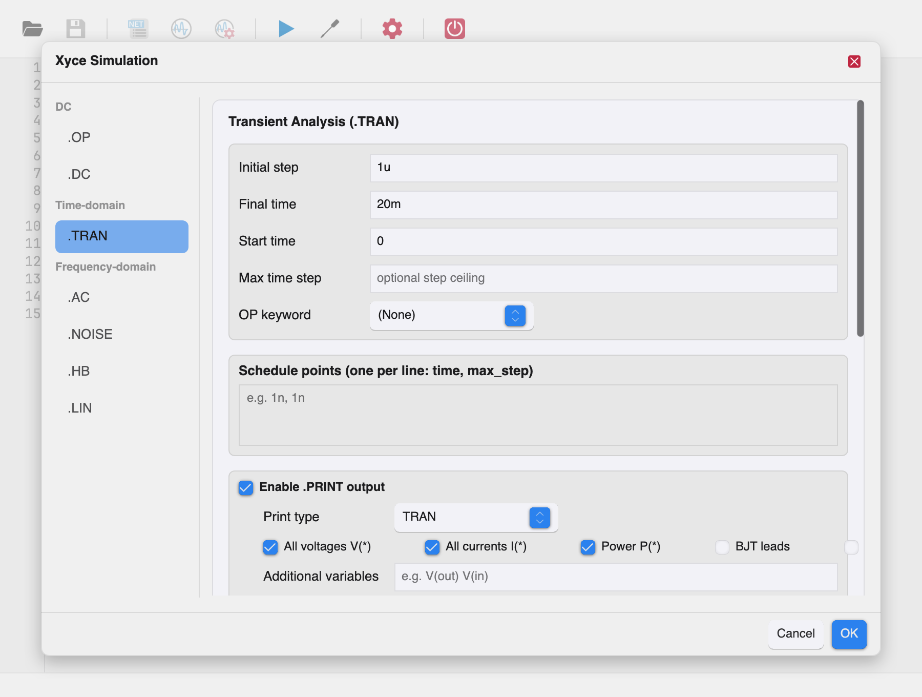
Click OK to apply the settings; the accepted directives are merged
into the netlist (before .END) and the simulation runs with them.
Cancel, Escape, or the ✕ button closes the dialog and discards
changes. Invalid input keeps the dialog open with the error shown in red
above the footer buttons.
Tip: clicking Run Simulation with no analysis configured opens this dialog first; the simulation starts after you accept it.
Ground node handling¶
Every analysis tab offers Replace ground (GND) with 0 (checked by
default). When enabled, all GND references in the netlist are replaced
with the node name 0 before simulation. This is required by Xyce,
which uses 0 as the global ground node. Leave it on unless your
netlist already uses 0 for ground.
Time and frequency values¶
All numeric fields accept standard SPICE engineering suffixes: 1n,
25m, 5u, 10MEG, 1G, ...
Operating Point (.OP)¶
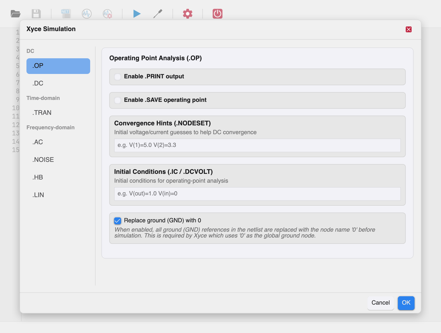
The operating point analysis computes the DC bias point of the circuit: all node voltages with the independent sources at their nominal values.
.PRINT output options¶
Enable .PRINT output to generate a printable output file of the operating point, then select what to include:
| Option | Meaning |
|---|---|
| All voltages V(*) | Every node voltage |
| All currents I(*) | Every source/device current |
| Power P(*) | Device power dissipation |
| BJT leads | BJT lead currents |
| FET leads | FET lead currents |
| Additional variables | Free-form list, e.g. V(out) V(in) |
- Format — output file format:
STD,NOINDEX,PROBE,TECPLOT,RAW,CSV,GNUPLOT,SPLOT.(default)uses the Xyce default (STD). See the Xyce reference guide for format details. - Output file — optional explicit path for the print file.
- Extra options — additional
.PRINToptions asKEY=VALUEpairs, e.g.WIDTH=20 PRECISION=12.
Save operating point (.SAVE)¶
Enable .SAVE operating point to write the converged bias point to a file for reuse in later runs (quick DC convergence of difficult circuits):
- Save as .NODESET / Save as .IC — the file is written as
.NODESETor.IClines. - Save file — optional output path.
- Level —
allornone. Note: if left at(default), Xyce creates no save file.
Convergence hints (.NODESET)¶
Initial voltage guesses to help the DC solver converge, e.g.
V(1)=5.0 V(2)=3.3. Xyce runs two solves: one holding the given values
as initial conditions, and one unconstrained starting from that
solution. Only voltages can be specified.
Initial conditions (.IC / .DCVOLT)¶
Conditions enforced for the entire operating-point solve, e.g.
V(out)=1.0 V(in)=0. Nodes not listed are free to converge. Only
voltages can be specified; unsolvable combinations are possible — see
the Xyce Users' Guide for guidance.
- Editing — the Initial Conditions field on the
.OP,.DCand.TRANtabs holds the line exactly as it will be emitted, without the.ICprefix (e.g.V(a)=2 V(b)=10); text that parses to no entry is rejected when the dialog is accepted. The other tabs (.AC,.NOISE,.LIN,.HB) keep the collected statements untouched (pass-through) for now. - Merge & dedup — every
.IC/.DCVOLTstatement in the netlist is collected top-down and written back as a single line before.END. A node named by several statements keeps its first position and takes the last value — the order Xyce applies them in — compared case-insensitively, because Xyce uppercases node names. - Which analyses use it — Xyce consumes
.ICin every analysis that computes a DC operating point:.OP,.DC,.TRAN,.AC,.NOISEand.LIN(which rides the AC sweep). WithNOOP/UICon.TRANthe values become the transient starting state and unspecified nodes start at 0. The reference guide documents no effect for.HB.
The .OP tab of the simulation parameters dialog also edits the
.OPTIONS NONLIN package values (the operating-point solver controls).
Transient (.TRAN)¶
The transient analysis computes the circuit response over an interval of time.
Time stepping¶
| Field | Meaning |
|---|---|
| Initial step | Initial time step, e.g. 1n. Xyce picks the actual first step as the smallest of this value, the step ceiling, and 1/200th of the time to the next breakpoint. |
| Final time | Simulation end time, e.g. 1u. |
| Start time | Optional. Time at which output starts; simulation always begins at t=0 regardless. Defaults to 0. |
| Max time step | Optional ceiling on the time step. Defaults to (final − start)/10, automatically refined around breakpoints. |
| OP keyword | NOOP (or its synonym UIC): skip the initial bias-point calculation and start from the specified initial conditions (.IC lines or capacitor IC parameters); unspecified values default to zero. (None) performs the normal bias-point calculation. |
Note: unlike classic SPICE, the first number on the .TRAN line is
the initial step, not the print interval.
Schedule points¶
The Schedule points field accepts one time, max_step pair per
line, e.g. 1n, 1n. This produces a {schedule(...)} clause: a maximum
time step of max_step is enforced while simulation time is between
time and the next listed time. A zero or negative step means no
enforced limit for that interval.
Directives¶
- .FFT directives — one per line, e.g.
.FFT V(out) START=1n STOP=1u NP=1024. See .FFT syntax below. - .FOUR directives — one per line, e.g.
.FOUR 1e6 V(out). See .FOUR syntax. - .MEASURE directives — one per line, e.g.
.MEASURE TRAN vout_max MAX V(out). See .MEASURE syntax. - .PLOT directives — one per chart, e.g.
.PLOT V(out) abs(I(R1)). They declare the charts the run opens and are not edited here; see The .PLOT Directive.
.PRINT output options¶
Same options as Operating Point plus a Print
type selector: TRAN (normal transient output) or TRANADJOINT
(transient adjoint sensitivity output). The print type defaults to
TRAN.
The .TRAN tab of the simulation parameters dialog also edits the
.OPTIONS TIMEINT, NONLIN-TRAN, LOCA, FFT and OUTPUT package
values.
DC Sweep (.DC)¶
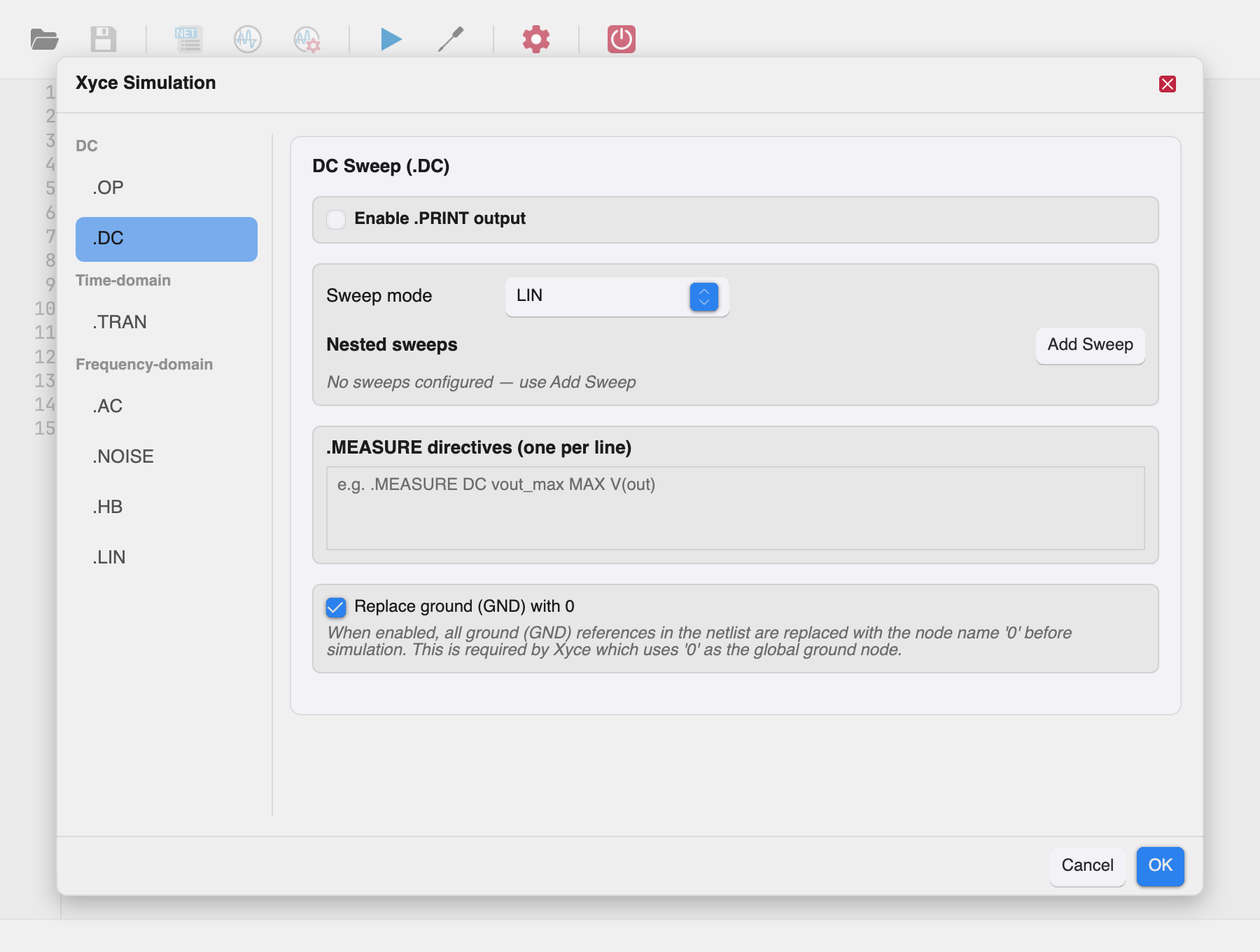
The DC sweep analysis steps one or more circuit parameters and computes the bias point at each value.
Sweep modes¶
| Mode | Fields | Meaning |
|---|---|---|
LIN |
Start, Stop, Step | Linear sweep from start to stop in increments of step. If stop < start, the step must be negative. |
DEC |
Start, Stop, Points | Logarithmic sweep by decades; Points is the number of points per decade. Stop must be larger than start. |
OCT |
Start, Stop, Points | Logarithmic sweep by octaves; Points is the number of points per octave. Stop must be larger than start. |
LIST |
— | Explicit list of values (configured in the nested sweeps table). |
DATA |
Data table | Sweeps from a .DATA table defined in the netlist. |
Nested sweeps¶
The Add Sweep button appends sweep rows; each row is one nested sweep dimension. A row contains:
- Variable — the swept source/parameter name, e.g.
V1,R1,TEMP. - Start / Stop — sweep range.
- Step (LIN only) or Points (DEC/OCT) or List values
(LIST, space-separated, e.g.
0 1 2 5).
Multiple rows produce nested sweeps (all combinations of the outer sweep with each inner sweep).
Validation¶
The dialog reports errors such as:
DC DATA sweep requires a data table nameDC <MODE> sweep requires at least one sweep variable- per-row errors:
sweep variable is required,start value is required,stop value is required,step value is required,points value is required,points value must be a positive integer,start value must be greater than zero.
A rejected OK keeps the dialog open so you can correct the input; Cancel still discards everything.
Directives and .PRINT¶
- .MEASURE directives as for transient, e.g.
.MEASURE DC vout_max MAX V(out). - Print type:
DCorHOMOTOPY; includes the Power option.
Uncertainty quantification (.PCE)¶
The DC and transient pages carry a shared Uncertainty quantification
(.PCE) section (Xyce Reference Guide §2.1.27). .PCE runs a fully
intrusive Polynomial Chaos Expansion on top of the .DC or .TRAN
analysis: the circuit is evaluated at quadrature points of the
distribution and the uncertainty propagates from inputs to outputs.
- Uncertain parameters — one row per sampled parameter with a name
(any parameter valid for
.STEP), a distribution type and two value fields:uniform→ lower/upper bounds,normal→ mean/standard deviation,gamma→ alpha/beta. - Expression-based inputs (useExpr) — when enabled, the random
inputs come from expression operators such as
AGAUSSandAUNIFand the parameter table is ignored. - .OPTIONS PCES package — one
key=valueentry per line; the requiredOUTPUTSentry lists the outputs for which statistics are computed (e.g.OUTPUTS={V(out)}); further entries areCOVMATRIX,SAMPLE_TYPE,SEED,OUTPUT_SAMPLE_STATS,RESAMPLE,OUTPUT_PCE_COEFFS,SPARSE_GRIDandSTDOUTPUT. - .PRINT PCE output — enables the companion print directive; extra
options accept
OUTPUT_SAMPLE_STATS=true(mean, meanplus, meanminus, stddev and variance) andOUTPUT_ALL_SAMPLES=true(all quadrature points).
The dialog rejects a PCE configuration with mismatched list lengths or
missing distribution values (e.g. PCE parameter R1: a normal
distribution requires means) and keeps the dialog open for corrections.
The .DC tab of the simulation parameters dialog also edits the
.OPTIONS NONLIN and LOCA package values.
AC Analysis (.AC)¶
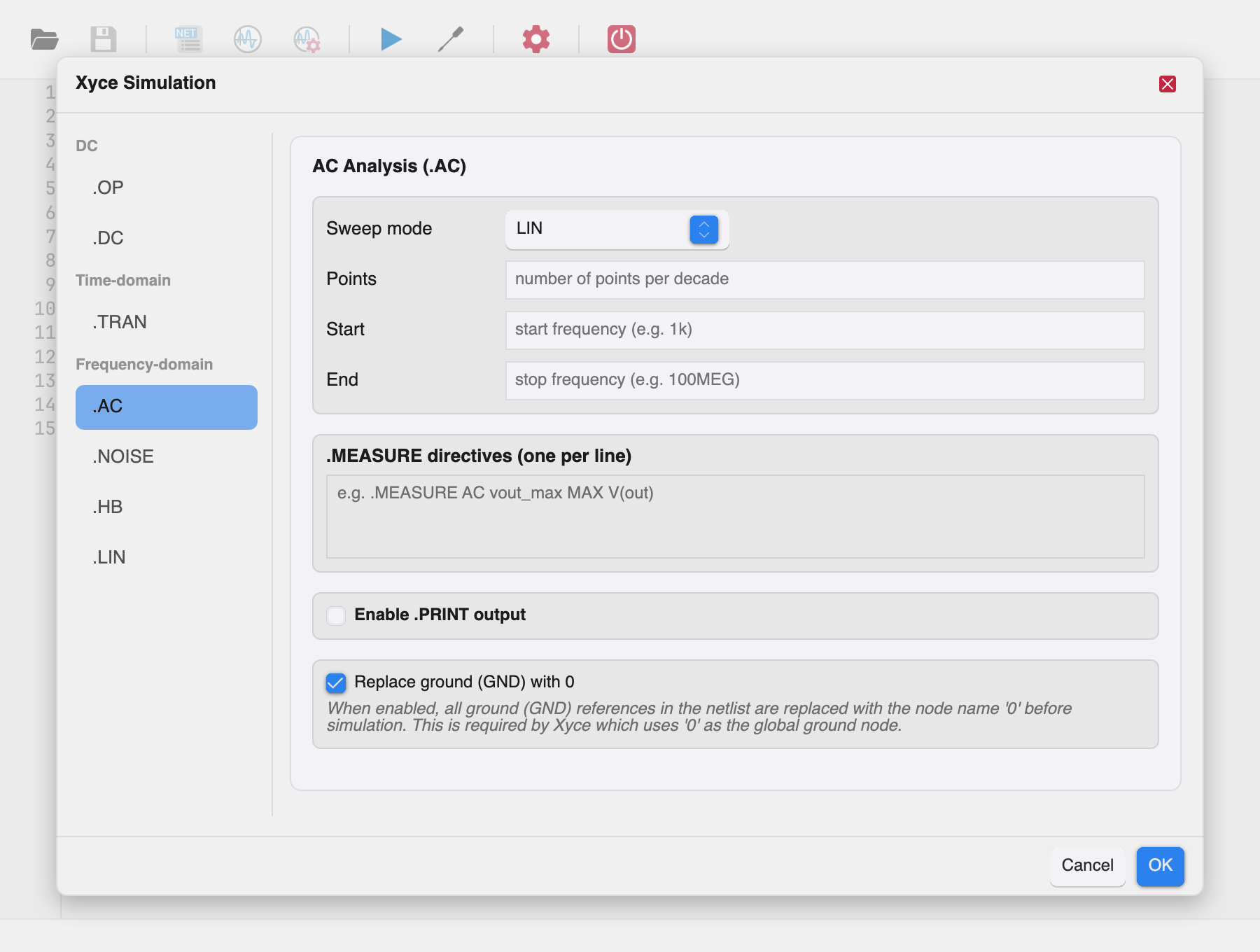
AC analysis linearizes the circuit around its DC bias point and computes the frequency response over a range of frequencies.
Sweep¶
| Field | Meaning |
|---|---|
| Sweep mode | LIN (linear), DEC (per decade), OCT (per octave), or DATA (values from a .DATA table). |
| Points | Number of points per decade/octave (DEC/OCT) or in the sweep (LIN). Integer ≥ 1. |
| Start / End | Frequency range in Hz, e.g. 1k … 100MEG. End must not be less than start; both must be greater than zero. |
Switching the sweep mode clears the fields of the previous mode.
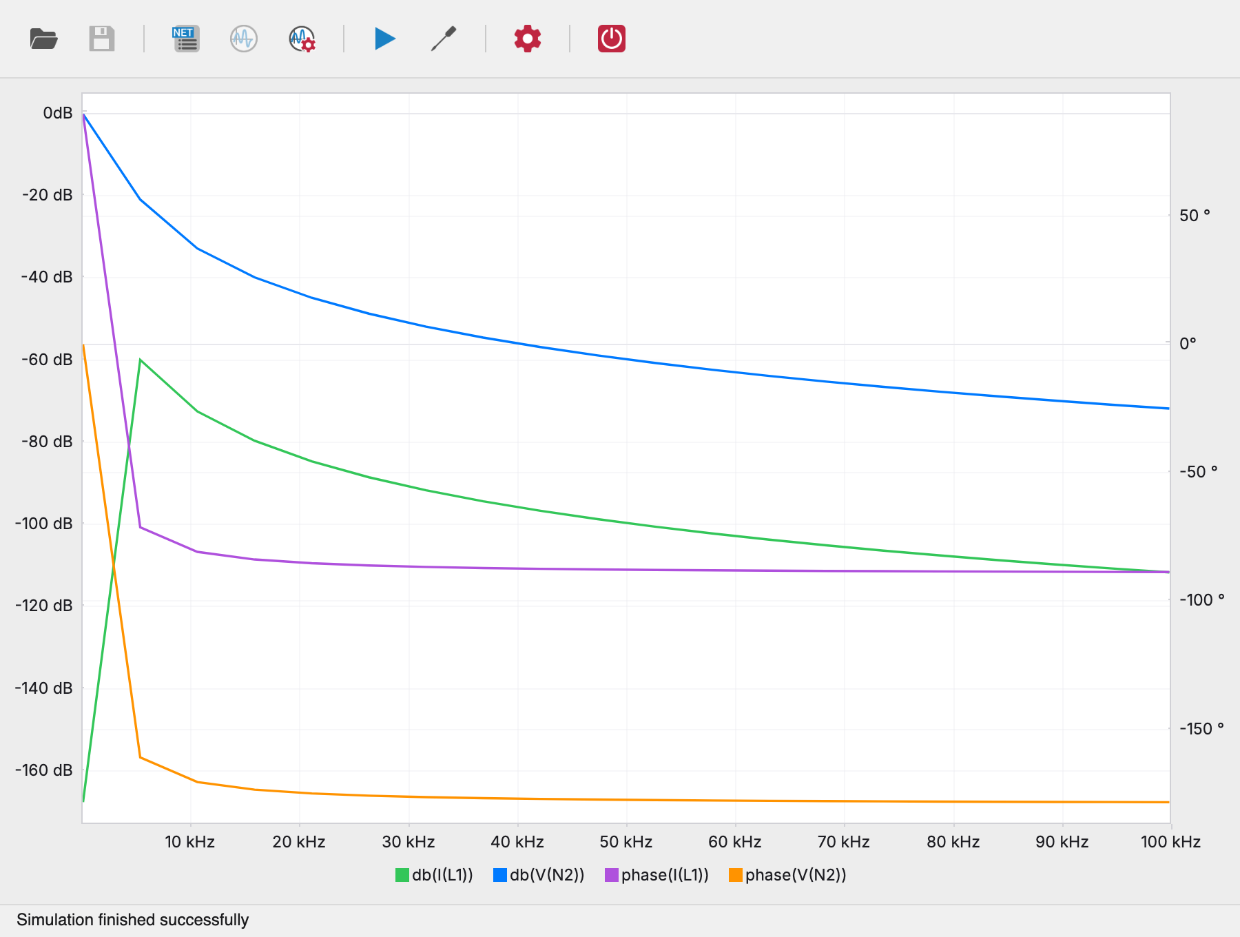
Note: sweeping magnitude and phase of an AC source with DATA is
supported, but nonlinear device parameters cannot be swept inside AC
analysis — use a .STEP directive for that.
Directives and .PRINT¶
- .MEASURE directives e.g.
.MEASURE AC vout_max MAX V(out). - Print type:
ACorAC_IC(AC initial conditions). Power calculations are not available for AC analysis.
The .AC tab of the simulation parameters dialog also edits the
.OPTIONS LINSOL-AC package values.
Noise (.NOISE)¶
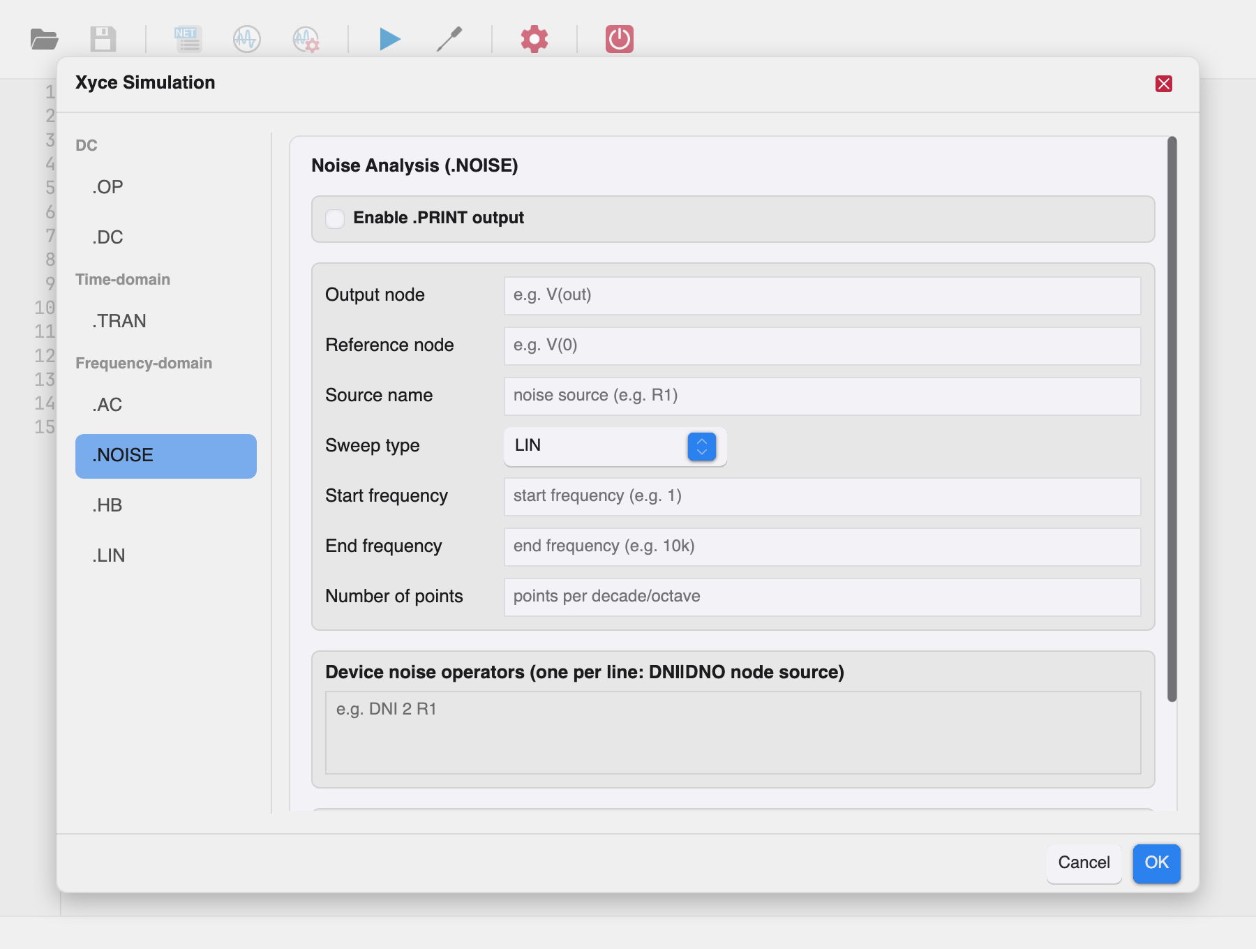
Noise analysis computes the small-signal noise response of the circuit over a range of frequencies, linearized around the bias point.
Noise configuration¶
| Field | Meaning |
|---|---|
| Output node | Node where total output noise is measured, e.g. V(out). |
| Reference node | Optional. Noise is computed as V(output) − V(ref); defaults to ground. |
| Source name | Name of the independent source the input noise is referred to, e.g. VIN. |
| Sweep type | LIN, DEC, OCT, or DATA. |
| Start frequency / End frequency | Frequency range; end must not be less than start, both greater than zero. |
| Number of points | Points per decade/octave (DEC/OCT) or in the sweep (LIN). Integer ≥ 1. |
| Data table | .DATA table name (for the DATA sweep type). |
Device noise operators¶
The Device noise operators field accepts one DNI|DNO node source
line per requested contribution, e.g. DNI 2 R1 — input-referred
(DNI) or output-referred (DNO) noise of a specific device.
Note: noise analysis is a relatively new Xyce feature; not all
device noise models are supported. Power is not available for noise
analysis. The print type is fixed to NOISE.
Harmonic Balance (.HB)¶
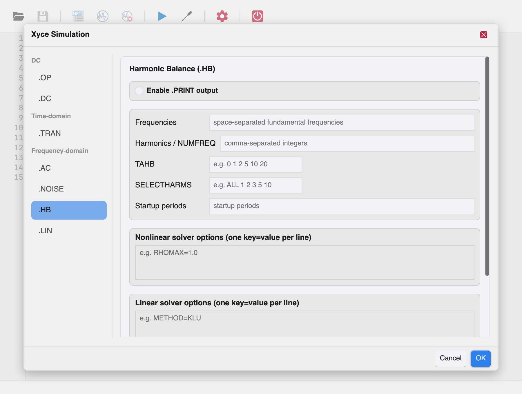
Harmonic balance computes the steady-state magnitude and phase of voltages and currents in a nonlinear circuit driven by periodic sources.
Frequency configuration¶
| Field | Meaning |
|---|---|
| Frequencies | Space-separated fundamental frequencies, e.g. 1e4 2e2. |
| Harmonics / NUMFREQ | Comma-separated integers selecting the harmonics to solve for. |
| TAHB | HB time-step schedule values, e.g. 0 1 2 5 10 20. |
| SELECTHARMS | Harmonic selection, e.g. ALL 1 2 3 5 10. |
| Startup periods | Number of startup periods simulated before the steady-state solve. |
Solver options¶
- Nonlinear solver options — one
KEY=VALUEpair per line, e.g.RHOMAX=1.0. - Linear solver options — one
KEY=VALUEpair per line, e.g.METHOD=KLU.
The available keys are documented in the Xyce reference guide
(.OPTIONS NONLIN-HB and .OPTIONS LIN).
Note: time-dependent B sources (and the same restriction applies to
E/F/G/H dependent sources in their time-dependent use) do not work with
HB analysis. Purely dependent usage works. The print type options are
HB (default), HB_FD (frequency domain), and HB_TD (time domain).
Linear Analysis (.LIN)¶
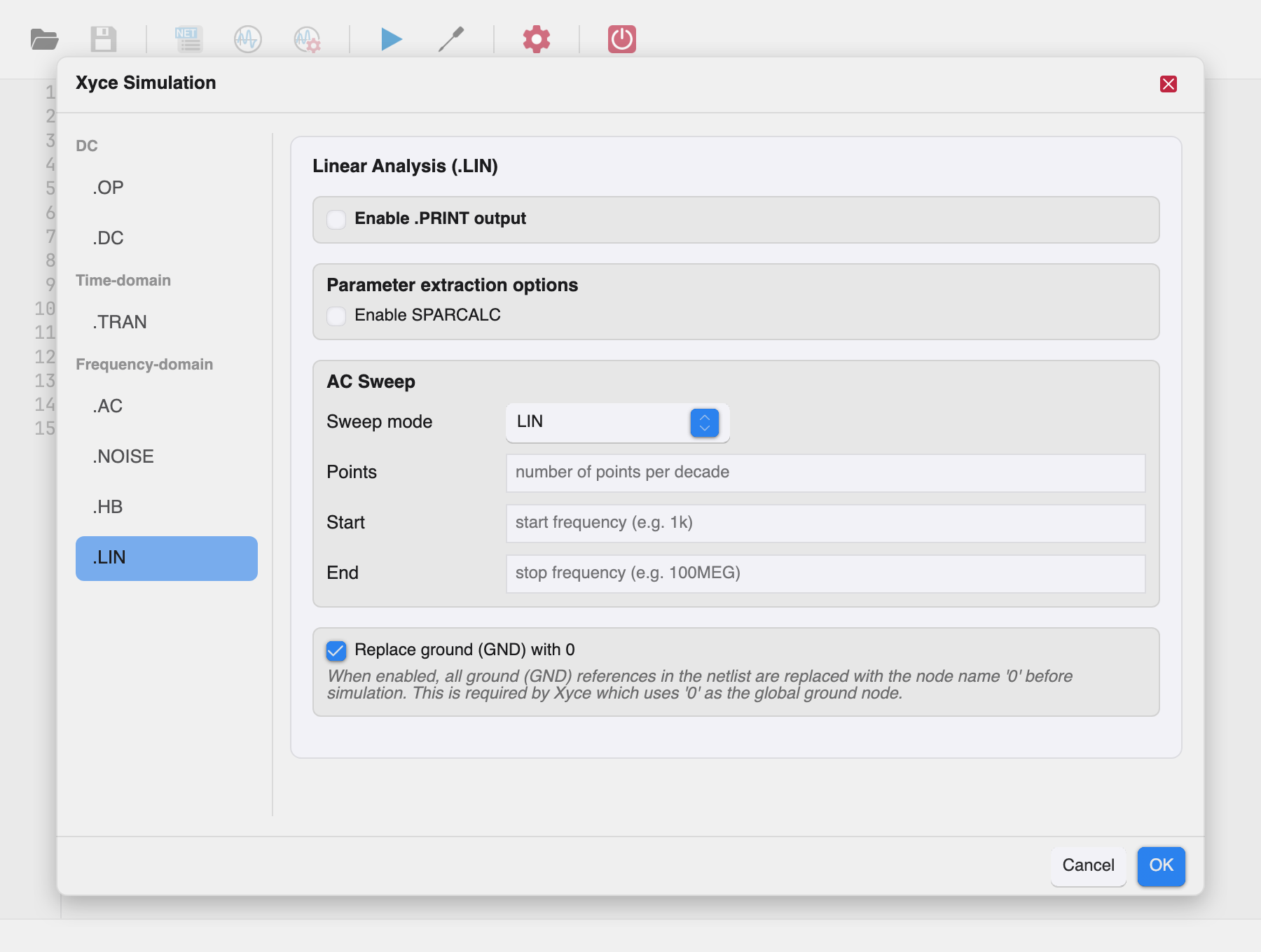
Linear analysis performs small-signal parameter extraction and writes the result as a Touchstone file — useful for S/Y/Z-parameter export into RF design tools.
Parameter extraction options¶
Enable SPARCALC to expose the extraction options:
| Field | Meaning |
|---|---|
| Format | TOUCHSTONE2 (default) or TOUCHSTONE (v1). |
| Type | Parameter type: S, Y, or Z. |
| Data format | RI (real–imaginary, default), MA (magnitude–angle in degrees), or DB (magnitude in dB–angle). |
| Output file | Path of the Touchstone file to write. |
| Width | Print field width in characters. |
| Precision | Decimal precision of the data. |
AC sweep¶
The extraction frequencies come from an AC sweep configured here, using
the same sweep modes as AC Analysis: LIN, DEC,
OCT, or DATA with Points/Start/End or a data table.
Note: with SPARCALC enabled, the .LIN analysis is done at the
frequency values specified on the .AC line. The print type is fixed
to AC; Power is available.
Print output options¶
All analysis tabs that produce waveform output share the .PRINT card:
- Enable .PRINT output — turn printing on.
- Variable selection —
All voltages V(*),All currents I(*),Power P(*),BJT leads,FET leads(availability varies by analysis), plus Additional variables as a free-form list. - Format —
STD,NOINDEX,PROBE,TECPLOT,RAW,CSV,GNUPLOT,SPLOT. - Output file — optional explicit file path.
- Extra options — additional
KEY=VALUEpairs (e.g.WIDTH=20 PRECISION=12).
Xyce Studio can plot all simulation output: the charts panel reads
the print file produced by the run in any plottable format — RAW
(.raw), PROBE (.csd), CSV (.csv), TECPLOT (.dat) and the
.prn formats (STD, NOINDEX, GNUPLOT, SPLOT). Therefore:
- always enable .PRINT output for the analysis you are running, and
- keep the Format on any plottable value —
(default)(STD) works.
Without a .PRINT line the run may complete but produce nothing
plottable, and the charts panel will stay empty.
To declare the charts a run should open, add
.PLOT directives to the netlist — they also make the
run print the quantities they plot, so a .PRINT line is no longer needed
just to get something on screen.
Options¶
Xyce Studio splits the managed .OPTIONS packages by the simulation
they apply to:
- The Options toolbar tool (right after Configure) edits the
simulation-agnostic packages:
DEVICE,LINSOL,PARSER,DIAGNOSTIC,DIST,MEASUREandRESTART. - The simulation-specific packages are edited in the Configure
dialog on the tab of their analysis:
TIMEINT,NONLIN-TRAN,FFTandOUTPUTon.TRAN;NONLINon.OPand.DC;LOCAon.DCand.TRAN;LINSOL-ACon.AC.
| Section | Option parameters | Simulation type |
|---|---|---|
DEVICE |
DEFAD, DEFAS, DEFL, DEFW, DIGINITSTATE, GMIN, MINRES, MINCAP, TEMP, TNOM, NUMJAC, VOLTLIM, B3SOIVOLTLIM, B3SOIGMINSCALING, ICFAC, MAXTIMESTEP, SMOOTHBSRC, RCCONST, VDSSCALEMIN, VGSTCONST, LENGTH0, WIDTH0, TOX0, DEBUGLEVEL, DEBUGMINTIMESTEP, DEBUGMAXTIMESTEP, DEBUGMINTIME, DEBUGMAXTIME | General |
TIMEINT |
METHOD, RELTOL, ABSTOL, RESTARTSTEPSCALE, NLNEARCONV, NLSMALLUPDATE, RESETTRANNLS, MAXORD, MINORD, NEWLTE, NEWBPSTEPPING, MASKIVARS, ERROPTION, NLMIN, NLMAX, DELMAX, MINTIMESTEPSBP, TIMESTEPSREVERSAL, DOUBLEDCOPSTEP, BREAKPOINTS, BPENABLE, EXITTIME, EXITSTEP | Transient (.TRAN) |
NONLIN |
NOX, NLSTRATEGY, SEARCHMETHOD, CONTINUATION, ABSTOL, RELTOL, DELTAXTOL, RHSTOL, SMALLUPDATETOL, MAXSTEP, MAXSEARCHSTEP, IN_FORCING, AZ_TOL, RECOVERYSTEPTYPE, RECOVERYSTEP, DEBUGLEVEL, DEBUGMINTIMESTEP, DEBUGMAXTIMESTEP, DEBUGMINTIME, DEBUGMAXTIME | DC / operating point |
NONLIN-TRAN |
same keys as NONLIN |
Transient (.TRAN) |
LINSOL |
TYPE, PREC_TYPE, USE_AZTEC_PRECOND, USE_IFPACK_FACTORY, IFPACK_TYPE, SHYLU_RTHRESH, TR_PARTITION, TR_PARTITION_TYPE, TR_SINGLETON_FILTER, TR_AMD, TR_GLOBAL_BTF, TR_REINDEX, TR_SOLVERMAP, ADAPTIVE_SOLVE, AZ_MAX_ITER, AZ_PRECOND, AZ_SOLVER, AZ_CONV, AZ_PRE_CALC, AZ_KEEP_INFO, AZ_ORTHOG, AZ_SUBDOMAIN_SOLVE, AZ_ILUT_FILL, AZ_DROP, AZ_REORDER, AZ_SCALING, AZ_KSPACE, AZ_TOL, AZ_OUTPUT, AZ_DIAGNOSTICS, AZ_OVERLAP, AZ_RTHRESH, AZ_ATHRESH, OUTPUT_LS, OUTPUT_BASE_LS, OUTPUT_FAILED_LS | General |
LINSOL-AC |
same keys as LINSOL |
AC (.AC) |
LOCA |
STEPPER, PREDICTOR, STEPCONTROL, CONPARAM, INITIALVALUE, MINVALUE, MAXVALUE, BIFPARAM, MAXSTEPS, MAXNLITERS, INITIALSTEPSIZE, MINSTEPSIZE, MAXSTEPSIZE, AGGRESSIVENESS, RESIDUALCONDUCTANCE | DC / transient (continuation) |
PARSER |
MODEL_BINNING, SCALE | General |
DIAGNOSTIC |
EXTREMA, EXTREMALIMIT, VOLTAGELIMIT, CURRENTLIMIT, DISCLIMIT, DIAGFILENAME | General |
DIST |
STRATEGY | General |
MEASURE |
DEFAULT_VAL, MEASDGT, MEASFAIL, MEASOUT, MEASPRINT, USE_CONT_FILES, USE_LTTM | General |
FFT |
FFT_ACCURATE, FFTOUT, FFT_MODE | Transient (.TRAN) |
OUTPUT |
INITIAL_INTERVAL, OUTPUTTIMEPOINTS, PRINTHEADER, PRINTFOOTER, SNAPSHOTS, ADD_STEPNUM_COL, PHASE_OUTPUT_RADIANS | Transient (.TRAN) |
RESTART |
PACK, JOB, INITIAL_INTERVAL, FILE, START_TIME | General |
SAMPLES |
NUMSAMPLES, SAMPLE_TYPE, OUTPUTS, MEASURES, COVMATRIX, SEED, OUTPUT_SAMPLE_STATS, REGRESSION_PCE, PROJECTION_PCE, RESAMPLE, OUTPUT_PCE_COEFFS, SPARSE_GRID, STDOUTPUT | Sampling (.SAMPLING) |
EMBEDDEDSAMPLES |
NUMSAMPLES, SAMPLE_TYPE, OUTPUTS, COVMATRIX, SEED, OUTPUT_SAMPLE_STATS, REGRESSION_PCE, PROJECTION_PCE, RESAMPLE, OUTPUT_PCE_COEFFS, SPARSE_GRID, STDOUTPUT | Embedded sampling |
In both dialogs, every option Xyce documents for the package (Reference
Guide §2.1.25) is listed as a row, whether or not the netlist uses it
yet; keys the netlist carries but the catalog does not document are
appended as extra rows. Options with a closed set of values (e.g.
METHOD = trap/gear) render a combobox with a <default> entry
that clears the option, free-text fields show the guide's default value
as placeholder, and bare flags (a key written without a value, e.g.
.OPTIONS FFT FFTOUT) offer a flag is set entry that keeps them, while
<default> removes the option. On accept, valued options are written
back as .OPTIONS <PKG> KEY=VALUE lines, kept bare flags as a bare
KEY, and every other empty field omits the option.
Both dialogs parse the options from the netlist when they open and
leave the configured analysis untouched.
The HB solver options (HBINT, NONLIN-HB, LINSOL-HB), the PCE
options (PCES) and the sensitivity options (SENSITIVITY) are edited
in their own analysis panels. The sampling options (SAMPLES,
EMBEDDEDSAMPLES) belong to .SAMPLING/.EMBEDDEDSAMPLING
statements, which Xyce Studio does not manage — their netlist values are
preserved but not editable. Standalone .OPTIONS lines without a
package keyword are not managed and stay verbatim in the netlist text.
Directives¶
.FFT directives¶
.FFT <output> [NP=<value>] [WINDOW=<value>] [ALFA=<value>]
     [FORMAT=<value>] [START=<value>] [STOP=<value>]
<output>— the signal to transform, e.g.V(out),I(L1).NP— number of FFT points, rounded to a power of two, minimum 4, default 1024.WINDOW— windowing function:RECT(rectangular, default),BART(Bartlett),BARTLETTHANN,BLACK/BLACKMAN,HAMM/HAMMING,HANN/HANNING.START/STOP— restrict the transform to a time range.
.FOUR directives¶
.FOUR <freq> <output> [output]*
Performs Fourier analysis over the last period (1/freq) of the
transient simulation and reports the DC component and the first nine
harmonics. Results are written to <netlist>.four# files.
.MEASURE directives¶
.MEASURE <AC|DC|NOISE|TRAN> <result name> <type> <variable> [FROM=...] [TO=...]
Common measure types:
| Type | Meaning |
|---|---|
AVG |
Average of the variable over the interval |
MAX / MIN |
Maximum / minimum value |
RMS |
Root-mean-square value |
PP |
Peak-to-peak value |
INTEG |
Integral of the variable |
FIND ... AT=<value> |
Value of the variable at a specific time/frequency |
WHEN <var>=<value> |
Time/frequency at which the variable crosses a value |
TRIG / TARG |
Rise/fall propagation measurements |
Results are printed to the output log (visible in the Simulation Output panel).
Measurements can be restricted with FROM=<value> and TO=<value>,
and expressions may reference .PARAM variables. The full syntax —
including FRAC_MAX, TD, error measures, and WHEN crossing
variants — is in the Xyce reference guide.